View Images Library Photos and Pictures. Electric Circuit Diagrams Lesson For Kids Video Lesson Transcript Study Com Central Air Conditioning Systems And Applications Intechopen Schematic Wikipedia Electrical Drawings And Schematics Overview

. 3 Draw The Schematic Diagram Given The Figures Belowfigure A Brainly Ph Wheatstone Bridge Circuit Theory Example And Applications The Schematic Diagram A Basic Element Of Circuit Design Analog Devices
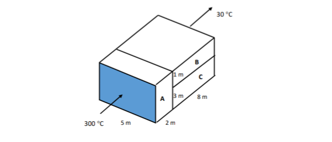 Answered Below Picture Shows The Composite Wall Bartleby
Answered Below Picture Shows The Composite Wall Bartleby
 Design Handbook Engineering Drawing And Sketching Related Resources Design And Manufacturing I Mechanical Engineering Mit Opencourseware
 Electrical Drawings And Schematics Overview
 Draw The Schematic Diagram Given The Figures Below Brainly Ph
 Solved 8 82 Figure P8 82 Shows The Schematic Diagram Of A Cogeneration 1 Answer Transtutors
 State Tables And State Diagrams
 A Circuit Is Shown In The Diagram Given Below A Find The Value Of R B Find The Science Electricity 9455821 Meritnation Com
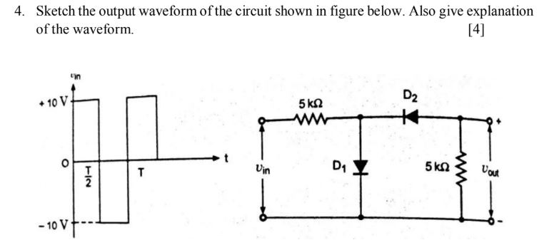 Answered 4 Sketch The Output Waveform Of The Bartleby
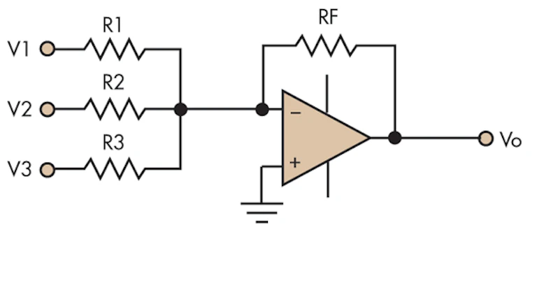 Efficiently Design An Op Amp Summer Circuit Electronic Design
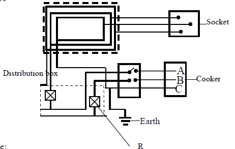 Figure Below Shows A Section Of A House Wiring System I Name I The Circuit Labelled F Ii The Terminals A And B Ii Give A Reason Why
 Solved Consider The Circuit Shown In Figure Below If The Function Impl Self Study 365
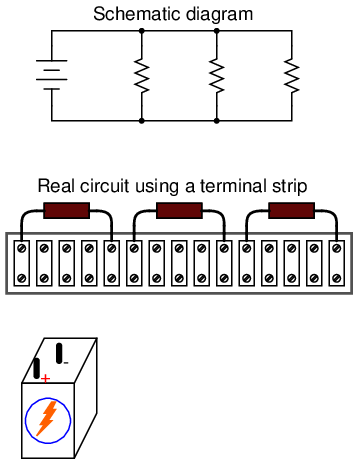 Lessons In Electric Circuits Volume I Dc Chapter 5
 Schematic Wikipedia
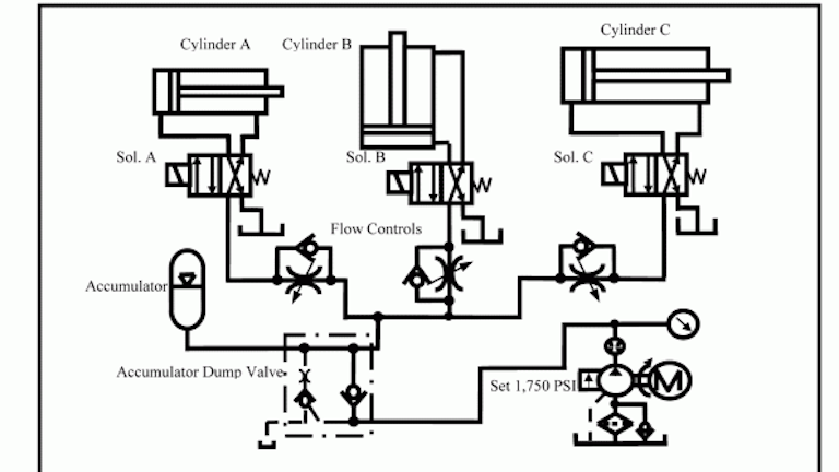 Chapter 5 Pneumatic And Hydraulic Systems Hydraulics Pneumatics
 Gate1996 24 A Gate Overflow
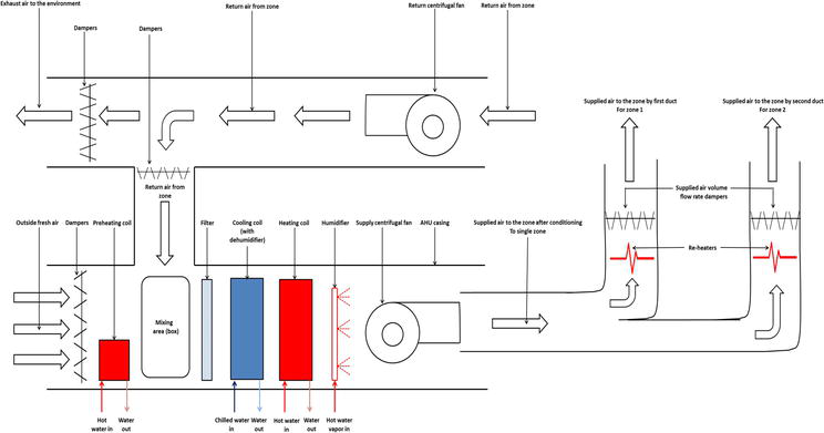 Central Air Conditioning Systems And Applications Intechopen
 Planet Analog When Gnd Isn T Gnd Single Ended Circuits Become Differential
 10 Simple Online Drawing Tools For Effective Thesis Diagrams Ilovephd
 What Is The Resistance Between A And B In The Figure Given Below Youtube
Current Through Resistor In Parallel Worked Example Video Khan Academy
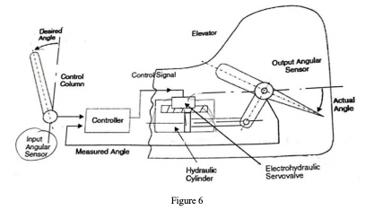 Figure 6 Below Gives The Schematic Diagram Of An A Chegg Com
 Lakhmir Singh Physics Class 10 Solutions For Chapter 1 Electricity Free Pdf
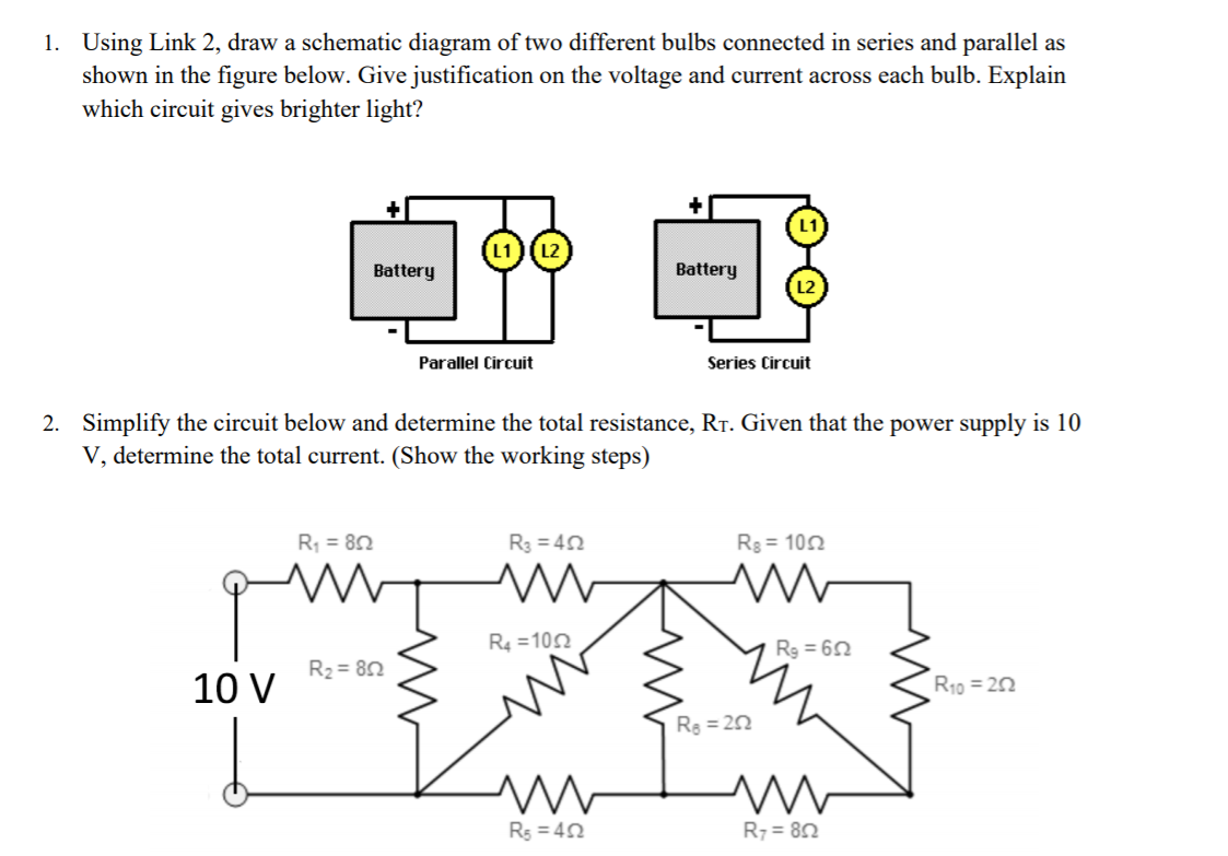 Solved 1 Using Link 2 Draw A Schematic Diagram Of Two D Chegg Com
 Creation Of Resistance Capacitance Model Of Component Symbols In The Schematic Library Programmer Sought
 Parallel Rlc Circuit And Rlc Parallel Circuit Analysis
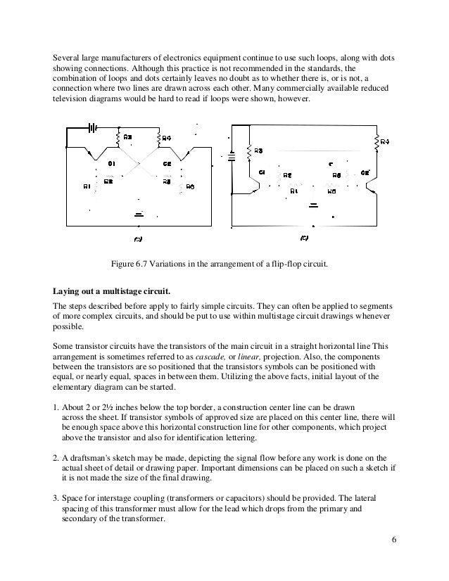
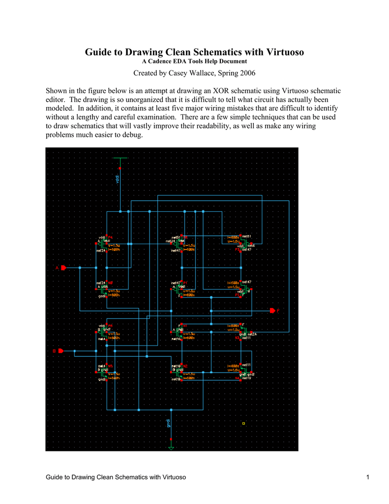 Guide To Drawing Clean Schematics With Virtuoso
 3 Logic Circuits Boolean Algebra And Truth Tables Dr Stienecker S Site
 Schematic Diagrams